User walkthrough
This tutorial guides you through using the Infrahub DC fabric demo as an end-user. You'll learn how to generate a network topology, create network services, and deploy configurations to a virtual lab environment.
What you'll learn
By completing this tutorial, you'll understand how to:
- Add a Git repository to Infrahub
- Generate a complete network topology
- Create and manage branches for change control
- Add Layer 2 and Layer 3 network services
- Create proposed changes and review diffs
- Deploy configurations to Containerlab
Before you begin
Complete the installation guide to ensure your environment is ready.
You should have:
- Infrahub running at http://localhost:8000
- Schema and initial data loaded
- Environment variables configured
- Containerlab installed (optional, for deployment testing)
Step 1: Add the repository to Infrahub
Infrahub needs access to this repository to execute generators, checks, and transforms. Add it via GraphQL or the UI.
- Via GraphQL
- Via the UI
Navigate to the GraphQL explorer at http://localhost:8000/graphql and execute:
mutation AddRepository{
  CoreReadOnlyRepositoryCreate(
    data: {
      name: { value: "infrahub-demo-dc-fabric" }
      location: { value: "https://github.com/opsmill/infrahub-demo-dc-fabric.git" }
    }
  ) {
    ok
    object {
      id
    }
  }
}
- Navigate to Unified Storage > Repositories
- Click Add Repository
- Fill in the details:
- Name:
infrahub-demo-dc-fabric - Location:
https://github.com/opsmill/infrahub-demo-dc-fabric.git - Commit:
main(or your current branch)
- Name:
- Click Save
Infrahub clones the repository and makes all scripts, templates, and queries available for use.
Step 2: Generate a network topology
The demo includes a topology generator that creates devices, interfaces, cabling, and BGP sessions based on topology definitions.
Run the generator
Generate the fra05-pod1 topology using the CLI:
poetry run infrahubctl run bootstrap/generate_topology.py topology=fra05-pod1
This generator:
- Reads the topology definition for
fra05-pod1 - Creates spine and leaf switches based on topology elements
- Generates interfaces for each device
- Creates physical connections between devices
- Configures BGP sessions between neighbors
- Adds devices to the topology group
Verify the topology was created
Navigate to Infrastructure > Devices in the UI at http://localhost:8000/objects/InfraDevice.
You should see devices like:
fra05-pod1-spine1,fra05-pod1-spine2, etc.fra05-pod1-leaf1,fra05-pod1-leaf2, etc.
Click on a device to explore its interfaces, connections, and BGP configuration.
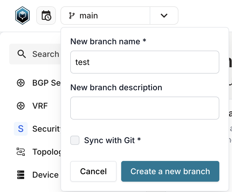
Step 3: Create a branch
Before making changes, create a branch to isolate your work.
- Via the UI
- Via the CLI
- Click the Branch dropdown in the top navigation
- Click Create Branch
- Enter a branch name (for example,
add-network-services) - Optionally add a description
- Click Create
poetry run infrahubctl branch create add-network-services
All subsequent changes will be made in this branch until you switch back to main.
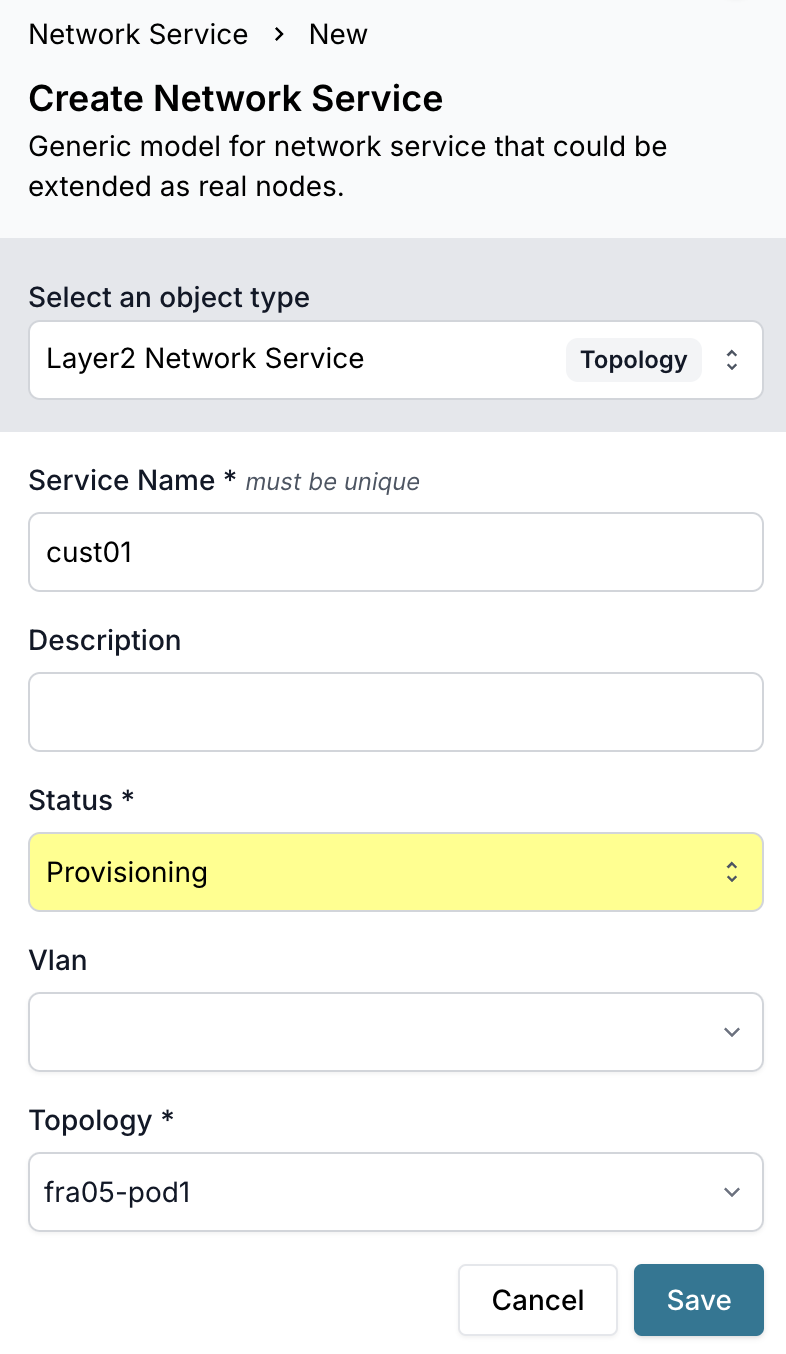
Step 4: Create a Layer 2 network service
Network services represent VLANs that span multiple devices in the topology.
Add the service
- Navigate to Network Service > Network Service at http://localhost:8000/objects/TopologyNetworkService
- Click Add Network Service
- Fill in the details:
- Name:
customer-vlan-100 - Type:
Layer2 - Topology: Select
fra05-pod1 - Description:
Customer VLAN for tenant isolation - VLAN ID:
100(optional, can be auto-allocated)
- Name:
- Click Save
Step 5: Add the service to the generator group
For the generator to process this service, add it to the network_services group.
Add to the group
- Navigate to Object Management > Groups at http://localhost:8000/objects/CoreStandardGroup
- Search for
network_servicesand click to open it - Click the Members tab
- Click Add Members
- Search for your service (
customer-vlan-100) and select it - Click Add
The network_services group is a trigger point. When you add a service to this group, the generator automatically creates VLANs, IP prefixes, and addresses when a proposed change is created.
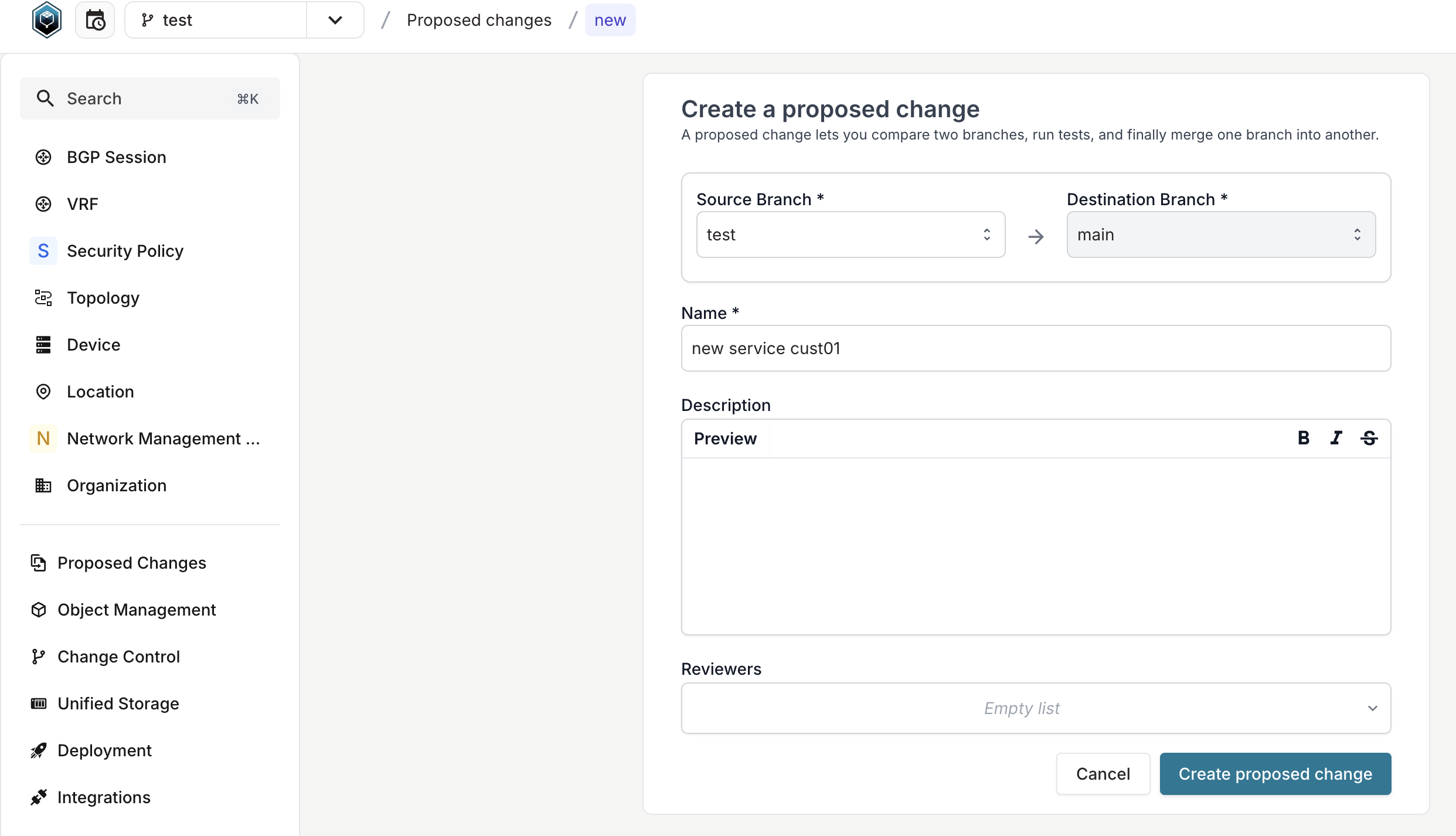
Step 6: Create a proposed change
Proposed changes are how you review and merge branch changes into main.
Create the proposed change
- Click the Branch dropdown in the top navigation
- Click Create Proposed Change
- Review the changes Infrahub detected
- Add a title (for example,
Add customer VLAN 100) - Optionally add a description
- Click Create
What happens next
When you create the proposed change:
- The
network_servicesgenerator runs automatically - It allocates IP prefixes from the location's resource pool
- It creates VLANs on appropriate devices
- It assigns IP addresses to device interfaces
- Configuration artifacts are regenerated with the new service
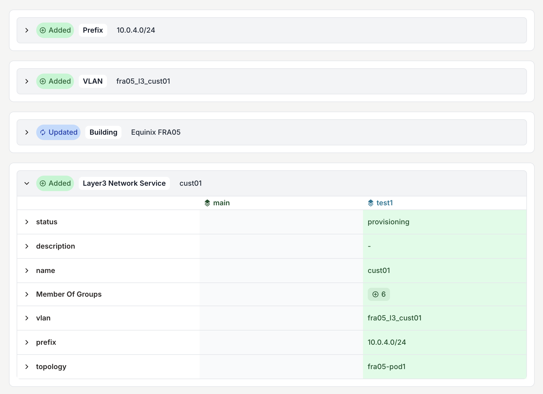
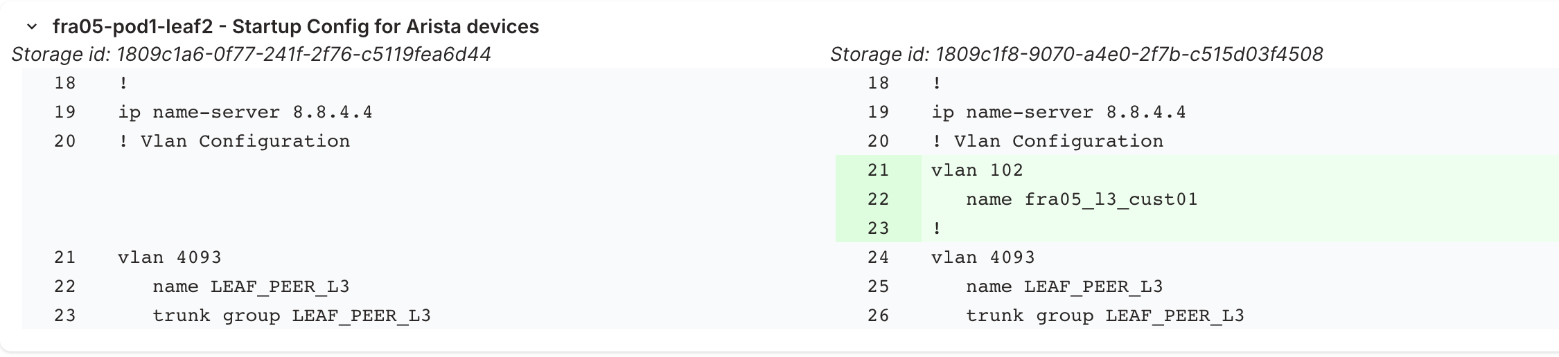
Review the diff
In the proposed change view:
- Click the Data tab to see object-level changes
- Click the Artifacts tab to see configuration diffs
You should see:
- New VLAN objects created
- New IP prefix allocations
- Updated device configurations including the new VLAN
Step 7: Add a Layer 3 network service
Layer 3 services include routing and IP addressing in addition to VLANs.
Create the L3 service
- Navigate to Network Service > Network Service
- Click Add Network Service
- Fill in the details:
- Name:
app-servers-vlan-200 - Type:
Layer3 - Topology: Select
fra05-pod1 - VRF: Select
Production - Description:
Application server segment
- Name:
- Click Save
Add to the generator group
Follow the same process as step 5 to add this service to the network_services group.
Update the proposed change
The proposed change automatically detects new changes in your branch. Refresh the view to see:
- Additional VLAN objects
- Routed IP prefixes with gateway addresses
- Updated device configurations with SVIs (switched virtual interfaces)
Step 8: Merge the proposed change
Once you've reviewed the changes and they look correct:
- In the proposed change view, click Merge
- Confirm the merge
- Infrahub merges your branch into main
Your network services are now part of the main branch and will be included in all future configuration generation.
Before merging, ensure all checks pass. If check_device_topology or other checks fail, investigate and resolve the issues.
Step 9: Test with Containerlab (optional)
Deploy your configurations to a virtual lab to test them.
Download artifacts
Run the script to download all generated configurations:
poetry run python3 scripts/get_configs.py
This creates a generated-configs/ directory with:
- Device startup configurations
- Containerlab topology file
Deploy the lab
Start the Containerlab topology:
sudo -E containerlab deploy -t ./generated-configs/clab/fra05-pod1.yml --reconfigure
This command:
- Creates Docker containers for each device
- Loads the startup configurations
- Connects containers based on the topology
Default credentials:
- Username:
admin - Password:
admin
DNS entries follow the pattern: clab-demo-dc-fabric-$nodeName
Verify connectivity
SSH to a device and verify the configuration:
ssh admin@clab-demo-dc-fabric-fra05-pod1-spine1
Check that VLANs exist:
show vlan
Check BGP neighbors:
show ip bgp summary
Destroy the lab
When finished testing, destroy the Containerlab topology:
sudo containerlab destroy -t ./generated-configs/clab/fra05-pod1.yml
Step 10: Experiment with topology validation
The demo includes a check that validates device counts match topology definitions.
Trigger a validation failure
- Create a new branch:
test-validation - Navigate to Topology > Topology at http://localhost:8000/objects/TopologyTopology
- Click on
fra05-pod1 - Click on Elements tab
- Find the element for leaf switches
- Change the Quantity from
8to6 - Click Save
- Create a proposed change
Review the check failure
In the proposed change view:
- Navigate to the Checks tab
- You should see
check_device_topologywith a failure status - Click to view the error details
The check reports: "Expected 6 leaf switches, found 8 in group."
This demonstrates how checks prevent inconsistencies from being merged.
Fix the issue
Either:
- Revert the quantity back to
8, or - Delete the extra leaf devices to match the new quantity
The check will pass once reality matches the topology definition.
What you've learned
Through this walkthrough, you've experienced:
- The Git integration workflow
- Topology generation from abstract definitions
- Branch-based change management
- Network service creation and automation
- Proposed change review and merging
- Artifact generation for configuration deployment
- Validation checks enforcing data consistency
- Virtual lab deployment for testing
Next steps
- Explore the developer guide to understand how generators and transforms work
- Review the concepts for deeper architectural understanding
- Experiment with creating custom security policies
- Modify templates to customize configuration output
- Create additional topologies for different locations
Troubleshooting
Generator doesn't run
- Ensure the repository is added to Infrahub
- Verify the service is in the
network_servicesgroup - Check that you created a proposed change (generators run during PC creation)
No prefix allocated
- Verify resource pools exist for the location (
supernet-fra05) - Check that pools have available address space
- Review generator logs for allocation errors
Containerlab deployment fails
- Ensure Docker images are available (check
CEOS_DOCKER_IMAGEenv var) - Verify sufficient system resources (CPU, memory, disk)
- Check for port conflicts with other running containers
- Review Containerlab logs:
sudo containerlab inspect -t ./generated-configs/clab/fra05-pod1.yml
Proposed change won't merge
- Resolve all failing checks first
- Review conflicts if another user modified the same objects
- Ensure you have write permissions on the branch